Air of Authority - A History of RAF Organisation


Home Page

Main Menu

Quick Menu

Members' Area

What New?

About this site

Reunions

Help Needed?

Glossary

Bibliography

Sign Guest Book

View Guest Book

Link to Amazon

Online Store

Contact Me


Plant Equipment - AP3036, Part 4 (1st Ed) & Part 5 (2nd Ed) - Concreting Equipment (became Part 6 (2nd Ed) - AL77)


(1st Ed) indicates that the Part/Section was in the original 1st Edition of AP3036.  (2nd Ed) indicates that the Part/Section was in the original 2nd Edition of AP3036, whilst the addition of AL? indicates which Amendment List, introduced this Part/Section following the original release of AP3036 (2nd Edition)


Millars' Batching Hoppers

Millars' Batching Hoppers

Description

The batching hopper arrangement shown above allows material to he stored in compartments and specified amounts to be released into tipping wagons which run on a light railway track.

The outfit consists of twin steel hoppers of 2 cu. yd. total capacity, mounted on a steel frame straddling the light railway track.

The hoppers are fitted at the bottom with discharge doors operated by hand levers.

Operation The above layout drawing shows a typical installation for feeding a 14/10 high discharge concrete mixer with aggregate. The aggregate may be loaded into the hoppers by means of a grab or a portable belt conveyor.
Data

The weight of a complete batching hopper unit is: -

Rails - 3½ cwt per set.

Hopper - 13¾ cwt

Wagons - 16 cwt, each.


Blaw-Knox Junior concrete weigh batcher (mobile)

Blaw-Knox Junior concrete weigh batcher (mobile) - working Blaw-Knox Junior concrete weigh batcher (mobile) - travelling

Description
  1. The Blaw Knox mobile Junior concrete weighbatcher is a small weighbatching equipment suitable for use in the field with batch type concrete mixers of either high-mounted or, standard type and of up to 21/14 cu. ft. capacity. It comprises: -

    1. AN ELEVATED MAIN HOPPER, of 20 cu. yd. total capacity, divided into three compartments for coarse and fine aggregates respectively. From the compartments the materials are discharged by gravity into a

    2. WEIGH HOPPER, where the required weights are shown on a scale dial. After being weighed, the unmixed materials are discharged by chute into the concrete mixer skip.  The main and weigh hoppers are mounted on

    3. PNEUMATIC-TYRED RUNNING GEAR, which permits the machine to be towed at convoy speeds by a suitable MT vehicle.

  2. The main hopper is fitted with flare-plates to facilitate filling and prevent spillage.  The flare-plates can be removed, and the main hopper lowered, to reduce the overall width and height when towing.  A suitable crane or other lifting tackle must be available when the equipment is to be erected, the weight of the flare-plates being approximately 27 cwt and that of the complete main hopper and flare-plate assembly 70 cwt.

  3. The weigh hopper is suspended by a series of weigh beams supported on knife-edge pivots and the weight-indicating mechanism incorporates an 18 in. dial of 2,240 lb. capacity with 5 lb. sub-divisions.  Three adjustable pointers can be positioned to show correct weights for the aggregates by accumulative weighing.

  4. Discharge of material from the main hopper to the weigh hopper is controlled by three guillotine type cut-off doors operated by separate handles at the side of the machine.  Discharge from the weigh hopper is controlled by a handle-operated gate type door.  The dial indicator can be assembled on either the left-hand or right-hand side of the machine to suit site conditions;  all operating handles should be assembled on the opposite side of the machine to the indicator dial.

  5. Brakes of the overrun type, and a detachable draw-bar, are fitted.  When the machine is in use, the chassis must be supported on timber packing spanning the full width of the frame and so arranged that the machine is level and the tyres are relieved of weight.  An adjustable leg is fitted to provide additional support for the weigh hopper and discharge chute and timber packing must also be provided as necessary beneath this leg.

This item of equipment appears to have been added to the 2nd Edition by the issue of AL57.

Machine Specification

Main hopper - 20 cu. yd. total capacity; detachable flare-plates; discharged by guillotine type doors.

  •  Capacity of end compartment - 6 cu. yd. each

  •  Capacity of centre compartment - 8 cu. yd.

Weigh hopper - 26 cu. ft. capacity; discharged by counterbalanced gate type door and chute

Dial indicator - Parsons, Type 6090/91; 2,240 lb. x 5 lb.

Running Gear

Suspension - 7-leaf, semi-elliptic springs     

Axle - Solid, square section

Wheel bearing - Taper roller

Wheels - Two, size 3.75 in. x 13 in.; 6-stud fixing, 18 mm. on 205 mm. PCD, 160 mm. bore

Tyres - Pneumatic, 25 in. x 6 in., 8-ply rating, standard tread

Brakes - Overrun type; wedge type brake shoes operating in 10 in dia. x 1-3/8 in. wide drums

Support leg - Adjustable 17 In. to 26 in.

Towing attachment - Detachable draw-bar, with 3 in. dia. towing eye

Data

Dimensions

  • In working position, draw-bar detached

    • Length - 11 ft 8½ in

    • Width - 13 ft 4½ in

    • Height - 18 ft 5 in


  • In towing position

    • Length - 13 ft 0 in

    • Width - 7 ft 6 in

    • Height - 9 ft 3 in

    • Track - 6 ft 10½ in

    • Ground Clearance - 11 in

    • Height of towing eye (draw-bar level) - 2 ft 6 in

Weight - 8,704 lb


Road Machines 20 cu yd concrete weigh batcher (mobile) Mk 1

Road Machines 20 cu yd concrete weigh batcher (mobile) Mk 1

Description
  1. The machine is intended for the accurate batching by weight of aggregate, sand, etc., prior to the loading of the material into concrete-making plant. The main hopper is divided into three separate compartments for the reception of different materials; discharge of material into the weighbucket from each compartment is controlled by gate-type doors located at the base of the hopper.

  2. The weight of material discharged into the weighbucket is shown on an indicator dial calibrated in 5 lb. divisions to a total of 1,400 lb.  After weighing, the unmixed materials are discharged from the bottom of the weighbucket into the loader skip of an adjacent concrete mixer.  The support frame of the weighbucket is pivoted and so arranged that the bucket may be swung horizontally from under the discharge doors of the hopper through a complete circle of approximately 3 ft. radius. This arrangement enables the weigh batcher to feed the skips of two mixers, one at the side and one at the rear, without further handling of material.

  3. The weigh batcher, when in operation with its hoppers full, will be of an approximate weight of 22 to 23 tons according to the materials being employed: because of this, it is essential that the plant be positioned on a hard standing, or on a working base of timber or some other suitable material, before operation.

  4. The Plant cannot be operated until it has been supported on packing and the chassis removed or alternatively, with the chassis disconnected and moved forward in relation to the superstructure.  It is advisable to remove the chassis completely so that it can be stored away from the dirty conditions that exist in the vicinity of concrete mixing equipment.

  5. The flareplates, and their internal dividing plates, forming an extension to the main hopper, are readily removable; they must be removed before any attempt is made to tow the plant.

  6. The trailer chassis on which the superstructure is mounted is fitted with Girling brakes operated by a Clayton Dewandre air pressure system and must only be towed by a vehicle fitted with a two line air pressure system.  Disconnection of the trailer air lines from the towing vehicle automatically applies the trailer brakes and no hand parking brake is fitted.  Release of the brakes, when disconnected from the towing vehicle, can only be effected by releasing the air pressure from the trailer air reservoir thus rendering the brakes ineffective until the weigh batcher is again connected to a towing vehicle.

  7. The Mark 1 model of the plant described here is generally similar to the Mark 2 model described below, but there are two important differences which must be noted. These are: -

    1. Wheel removal -  The wheels of the Mark I model cannot be removed from their hubs until the superstructure has been removed from the chassis.  The wheels of the Mark 2 model are easily removable

    2. Flareplates - Each flareplate of the Mark 1 model consists of two separate sections bolted together.  On the Mark 2 model each flareplate is a complete sub-assembly.

MT required for transportation -

  • 10 Ton tipper or any similar vehicle fitted with two line air pressure brakes.

This item of equipment appears to have been added to the 2nd Edition by the issue of AL77.

Operating Data

Capacities

  • Main hopper

    • Rear compartment: - 8.6 cu yd

    • Left-hand compartment -  6.6 cu. yd.

    • Right-hand compartment - 4.8 cu. yd.

  • Weighbucket  - 15 cu, ft. or 1,400 lb, whichever is the greater.

Working dimensions

Plant in working condition with trailer chassis removed and superstructure supported to give a 2 ft. 6 in. discharge height to the discharge door of the weighbucket.

Overall length, main hopper flareulates - 12 ft 6 in

Overall width, across flareplates - 11 ft 6 in       

Overall height, top of dividing plates - 15 ft 1 in

Loading height - 14 ft 3 in

Discharge height - 2 ft 6 in

Swing clearance for weighbucket - Add 4 ft 0 in to both the overall length and the overall width.

Road Machines 20 cu yd concrete weigh batcher (mobile) Mk 1 - Dimensions

Data

Dimensions - Partially dismantled, trailer chassis fitted, ready for towing

  • Overall length, rear of trailer chassis to front of tow-eye - 14 ft 2 in

  • Overall width, rear of superstructure - 7 ft 8 in

  • Overall height, top of superstructure - 11 ft 3 in

  • Track - 6 ft 8 in

  • Ground  clearance under chassis cross-members - 9 in

  • Tow-eye height, draw-bar level - 2 ft 5 in

  • Draw-bar, overhang from superstructure - 3 ft 4 in

  • Centre of tow-eye to centre of axle - 9 ft 2½

  • Turning circle radius, manhandled - 9 ft 5 in

General information

  • Maximum safe towing speed - 20 mph

  • Trailer brake connections - Clayton Dewandre quick-detachable couplings for two line air pressure brakes.

  • Electrical connections - Wandering lead and bayonet connector

  • Detachable items

    • Eight flareplate sections

    • Three dividing plates

    • Support brackets and angle sections

    • One bag of bolts

    • These items can be stowed in a space 7 ft. 6 in. x 4 ft. 9 in. x 4 ft. 0 in.

Weight 2,500 lb


Road Machines 20 cu yd concrete weight batcher (mobile) Mk 2

Road Machines 20 cu yd concrete weight batcher (mobile) Mk 2 - travelling position  Road Machines 20 cu yd concrete weight batcher (mobile) Mk 2 - working position

Description
  1. The machine is intended for the accurate batching by weight of aggregate, sand, etc., prior to the loading of the material into concrete-making plant. T he main hopper is divided into three separate compartments for the reception of different materials; discharge of material into the weighbucket from each compartment is controlled by gate-type doors located at the base of the hopper.

  2. The weight of material discharged into the weighbucket is shown on an indicator dial calibrated in 5 lb. divisions to a total of 1,400 lb.  After weighing, the unmixed materials are discharged from the bottom of the weighbucket into the loader skip of an adjacent concrete mixer. The support frame of the weighbucket is pivoted and so arranged that the bucket may be swung horizontally from under the discharge doors of the hopper through a complete circle of approximately 4 ft. radius. This arrangement enables the weigh batcher to feed the skips of two mixers, one at the side and one at the rear, without further handling of material.

  3. The weigh batcher, when in operation with its hopper full, will be of an approximate weight of 22 to 23 tons according to the materials being employed; because of this, it is essential that the plant be positioned on a hard standing, or on a working base of timber or some other suitable material, before operation.

  4. The plant cannot be operated until it has been supported on packing and the wheels removed or, alternatively, with the complete trailer chassis removed from the superstructure.  It is advisable to remove the chassis completely so that it can be stored away from the dirty conditions that exist in the vicinity of concrete mixing equipment.

  5. The flareplates, and their internal dividing plates, forming an extension to the main hopper are readily removable; they must be removed before any attempt is made to tow the plant.

  6. The trailer chassis is fitted with Girling brakes operated by a Clayton Dewandre air pressure system and must only be towed by a vehicle fitted with a two line air pressure system.  Disconnection of the trailer air lines from the towing vehicle automatically applies the trailer brakes and no hand parking brake is fitted.  Release of the trailer brakes, when disconnected from a towing vehicle, can only be effected by releasing the air pressure from the trailer air reservoir thus rendering the brakes ineffective until the weigh batcher is again connected to a towing vehicle.

  7. The Mark 2 model of the plant, described here is an improved version of the Mark 1 model describedabove.  The most important differences are:—

    1. Wheel removal. - The wheels of the Mark 2 model are readily removable; on the Mark 1 model, the wheels cannot be removed from their hubs until the superstructure has been removed from the chassis.

    2. Flareplates. - On the Mark 2 model, each flareplate is a complete sub-assembly; on the Mark 1 model, each flareplate is fabricated in two halves.

MT required for transportation -

  • 10 Ton tipper or any similar vehicle fitted with two line air pressure brakes.

This item of equipment appears to have been added to the 2nd Edition by the issue of AL77.

Operating Data

Capacities

  • Main hopper

    • Rear compartment: - 8.5 cu yd

    • Left-hand compartment -  6.5 cu. yd.

    • Right-hand compartment - 5.0 cu. yd.

  • Weighbucket  - 15 cu, ft. or 1,400 lb, whichever is the greater.

Working dimensions

Plant in working condition with trailer chassis removed and superstructure supported to give a 2 ft. 6 in. discharge height to the discharge door of the weighbucket.

Overall length, main hopper flareplates - 12 ft 10 in

Overall width, across flareplates - 11 ft 8 in       

Overall height, top of dividing plates - 15 ft 4 in

Loading height - 14 ft 6 in

Discharge height - 2 ft 6 in

Swing clearance for weighbucket - Add 2 ft 0 in to both the overall length and the overall width.

Data

Road Machines 20 cu yd concrete weight batcher (mobile) Mk 2 - Dimensions

Dimensions - Partially dismantled, trailer chassis fitted, ready for towing

  • Overall length, rear of trailer chassis to front of tow-eye - 15 ft 0 in

  • Overall width, rear of superstructure - 7 ft 8 in

  • Overall height, top of superstructure - 11 ft 5 in

  • Track - 6 ft 3 in

  • Ground  clearance under chassis cross-members - 1 ft 2 in

  • Tow-eye height, draw-bar level - 2 ft 6 in

  • Draw-bar, overhang from superstructure - 4 ft 9 in

  • Centre of tow-eve to centre of axle - 9 ft 2 in

  • Turning circle radius, manhandled - 9 ft 5 in

General information

  • Maximum safe towing speed - 20 mph

  • Trailer brake connections - Clayton Dewandre quick-detachable couplings for two line air pressure brakes.

  • Electrical connections - Wandering lead and bayonet connector

  • Detachable items - Four flareplates, two dividing plates, and four corner pieces. Can be stowed in a space 13 ft. 0 in. x 4 ft. 9 in x 2 ft. 0 in.

Weight 2,500 lb


Millars' Concrete Mixer Type 14/10, Standard, Mk I & Mk II

Millars' Concrete Mixer Type 14/10, Standard, Mk I & Mk II   Millars' Concrete Mixer Type 14/10, Standard, Mk I & Mk II

Description
  1. The Millars' concrete mixer, Type 14/10, is of the non-tilting, rotary closed drum type. The mixer consists of a power-operated loader bucket, discharge chute, water tank and steel mixing drum which rotates on steel rollers. The complete unit is mounted on a steel frame with four steel-tyred road wheels; the front axle is pivoted centrally and carries a tubular towing bar terminating in a standard trail-eye. The mixer is powered by a Ruston diesel engine, 1VSO or 1VSH, or by a Ruston gasoline/kerosine engine, Type PB,

  2. The mixer must be towed only for short distances and at a speed not exceeding 6 m.p.h.

MT required for transportation -

  • Bedford OWST, OWL or similar (for towing)

  • Hands or Templewood trailer (for transportation)

This item of equipment first appeared in AP3036 (1st Edition) but this entry has been updated to AL38, 2nd Edition

Engines

Mk  I - Ruston & Hornsby, Type PB, single cylinder, water-cooled, petrol/paraffin engine:

Mk II - Ruston & Hornsby, Type 1VSO or 1VSH,  single cylinder, water-cooled, Diesel engine:

Both engines - Swept volume - 1.093 cc:  BHP - 7½ at 1,000 rpm

Operating Data 10 cu ft of concrete per operation
Data

 Working weight - 2 tons 13 cwt.

Overall dimensions: -  

  • Length - 10 ft 1in.  

  • Width with loader bucket up for transporting - 8 ft 0 in

  • Width with loader bucket down for operation - 11 ft 9 in.

  • Height with loader bucket up for transporting - 9 ft 7 in

Fuel consumption (Mk I) - 6 pints per hour. 


Millars' Concrete Mixer Type 14/10, High Discharge, Mk I & Mk II

Millars' Concrete Mixer Type 14/10, High Discharge, Mk I & Mk II

Description

The 14/10 high discharge mixer is identical with the standard mixer (see entry above) of the same capacity, except that the whole mixing unit is raised on a steel gantry mounted on four steel road wheels and fitted with a towing bar. The difference between the two Marks is the same as for the standard mixer.

The height of discharge of mixed concrete is 6 ft. 6 in. above ground level in order that dumpers and lorries may receive mixes direct from the discharge chute.

Operation As the Standard models shown above.
Data

Working weight - 3 tons 4 cwt

Overall dimensions: -   

  • Length - 12 ft. 5 in

  • Width with loader bucket down - 12 ft 10 in

  • Width with loader bucket detached - 8 ft 0 in

  • Height - 13 ft 6 in

Fuel consumption (Mark I) - 6 pints per hour.


Millars' Concrete Mixer Type 10/7 (Trailer Mounted)

Millars' Concrete Mixer Type 10/7 (Trailer Mounted)

Description
  1. The 10/7 mixer, illustrated above, is of the non-tilting rotary closed drum type.  The mixer consists of a power-operated loader bucket, discharge chute, water tank and steel mixing drum rotating on steel rollers.  The power unit is a Bamford 5 hp petrol engine. The complete unit is fixed on a steel frame mounted on two pneumatic-tyred and semi-elliptic sprung road wheels; a towing bar and overrun brakes are also fitted.

This vehicle was shown in AP3036 (1st Edition) so was probably in use before 1944.  When AP3036 (2nd Edition) was issued, it was still included.

MT required for transportation -

  • Hands or Templewood trailer (for transportation)

  • AEC, Matador, 4x4, Tractor (for Towing)

Operation

The output of mixed concrete per operation is 7 cu. ft.  The number of operations per hour varies according to the individual conditions, from 10 to 15, thus giving an output per 8 hour day of from 21 to 31 cu yd of concrete.

Great care must be taken to level up the machine both ways before commencing work, and all weight must be taken off the pneumatic tyres by means of the jacks fitted. Failure to do this may result in a strained frame, undue wear of the mixing drum rollers, and damage to the pneumatic tyres.

The mixer should be set up if possible so that the prevailing wind does not blow dust and cement into the engine.

The length of time required for mixing depends on the materials and the amount of water in the mix.

Particular care must be taken when shutting down for meal times and at the close of the day's work to ensure that the mixing drum is left free from concrete, by washing out with gravel (or stone) and water.

The mixer may be towed for considerable distances, but at speeds not exceeding 20 mph and whenever moved should be inspected on arrival at the new site to ensure all bolts and nuts are tight and that no damage has resulted due to transportation.

Data

Working weight  - 4,592 lb

Overall dimensions: -

  • Length with loader bucket down - 10 ft 4 in.

  • Length with loader bucket up - 7 ft 3 in

  • Width - 7 ft 5 in

  • Height - 8 ft 2 in

Tyres - 27.00 x 6 in

Fuel consumption - 3½ pints per hour.


Millars' Concrete mixer, Type 7 NT

Millars' Concrete mixer, Type 7 NT

Description
  1. The 7 NT mixer is powered by a single-cylinder, water-cooled, diesel engine developing 5 hp at 1,000 rpm.and is of the rotary non-tilting drum type. Loading is by a power-operatcd bucket, controlled by a single lever operating both clutch and brake, water is added to the "mix" from a metering tank on the top of the unit, and the 'mix" is discharged by a tilting scoop on the opposite side.

  2. The unit is mounted on four wheels, either plain steel drums or spoked with pneumatic tyres.  Jacks are fitted above the front axle to steady the unit during operation; steering is by draw-bar and centrally-pivoted front axle, and the draw-bar terminates in a standard circular towing eye.

  3. The drive from the engine is transmitted through a direct-coupled shaft to a chain-driven countershaft carrying the bevel drive for the drum and a sprocket forming the power supply for the loader hoist shaft.

  4. The mixing drum rotates on rollers and is driven from the first motion countershaft bevel through an external ring gear; curved blades are fitted inside the drum to agitate the "mix' as the drum rotates. The discharge scoop is tilted into the drum by the operation of a lever at the rear of the mixer, catching the "mix' as it falls from the upper half of the drum and directing it into the barrow or skip.

MT required for transportation -

  • Hands or Templewood trailer (for transportation)

  • Bedford OWST or similar (for Towing)

This item of equipment appears to have been added to the 2nd Edition by the issue of AL31.

Engine

Ruston Hornsby IVTH:  Capacity - 809 cc:  BHP - 5 at 1,000 rpm

Operation

Cone clutch on engine shaft to countershaft; chain drives to drum bevel gear and loader shaft.  Release of loader brake lowers loader to ground; loader filled to capacity gives correct charge.  The loader is raised by moving the lever in the reverse direction to engage the clutch.  The discharge chute is inserted in the drum by moving the lever at the left rear of the plant.

Technical Data

Model Running gear - 4-wheeled trailer, steel wheels or pneumatic tyres; pivoting axle beam.  Unsprung, with rocking beam axle and jacks.

Mixing drum - Rotary non-tilting 7 cu. ft. capacity; fixed steel agitator blades. Scoop to discharge "mix" into barrows. Water tank meters supply into drum.

Controls - Water tank control, loader clutch and brake (combined) and discharge scoop lever

Working weight  - 2 tons ¼ cwt

Overall dimensions: -

  • Length (including draw-bar) - 11 ft 9 in.

  • Width (loader raised, discharge chute in) - 7 ft 0 in

  • Width (loader lowered) - 10 ft 4 in

  • Height (loader raised) - 8 ft 9 in

  • Height (loader lowered) - 8 ft 0 in

  • Wheelbase - 6 ft 9 in

  • Track - 6 ft

  • Height of discharge - 2 ft 4 in


Millars' Concrete mixer, Type 10NT

Millars' Concrete mixer, Type 10NT

Description
  1. The Millars' mixer, Type 10 NT is of the non-tilting drum type, and embodies a power-operated loader, a self-measuring water supply system and a manually controlled discharge chute which can be used to cut off the discharge when the barrow or skip is fully loaded.  The unit is mounted on a four-wheeled pneumatic-tyred trailer with a tubular draw-bar terminating in a standard towing eye.

  2. The unit is entirely self-sufficient in operation, apart from the necessity of connecting a water supply to the metering cistern.  Stabilizers are fitted to the wheels on the loading side to prevent flexing of the tyres due to the side load of the filled loader bucket.  All control levers are grouped at the rear end of the plant, enabling one operator to raise and lower the loader, add the correct amount of water to the 'mix" and control the discharge chute.  The amount of water admitted to each "mix" is controlled by a pre-set hand wheel on the water tank, the scale being calibrated in gallons and pounds.

  3. The 10 NT mixer is powered by a Ruston Hornsby diesel engine developing 7½ hp at 1,000 rpm, driving through a centrifugal clutch and roller chains to the drum gear and loader countershaft.

MT required for transportation -

  • Hands or Templewood trailer (for transportation)

  • Bedford OWST, OWL or similar (for Towing)

This item of equipment appears to have been added to the 2nd Edition by the issue of AL31.

Engine

Ruston Hornsby IVSH or IVSO:  Capacity - 1,093 cc:  BHP - at 1,000 rpm

Operation

Centrifugal clutch operates at 450-550 rpm, enabling engine to be started in neutral.  The loader control lever lowers the loader bucket to the ground; loader filled to capacity is correct charge of aggregate.  The water valve controls are operated in turn, half the amount being admitted before the aggregate to wash the drum, and half after the drum is filled.  The loader is raised by moving the lever inwards, towards the centre of the machine, so engaging the clutch and rotating the winding shaft.  The discharge chute is inserted in the drum by operation of the lever on the left of the group.

Technical Data

Running gear - 4-wheeled pneumatic-tyred trailer with centre-point steering.  Unsprung, with rocking-beam front axle mounting and jacks.  Stabilizers fitted to right side wheels only.

Mixing drum - Rotary non-tilting; 10 cu. ft. capacity; fixed steel agitator blades scoop to discharge "mix" into barrows.  Water tank meters supply into drum.

Controls - Two water valves, loader clutch and brake (combined) and discharge scoop lever.

Working weight  - 2 tons 15 cwt

Overall dimensions: -

  • Length (including draw-bar) - 13 ft 4 in.

  • Width (loader raised, discharge chute in) - 8 ft 2 in

  • Width (loader lowered) - 12 ft 0 in

  • Height (loader raised) - 10 ft 3 in

  • Height (loader lowered) - 9 ft 1 in

  • Wheelbase - 7 ft 0 in

  • Track - 6 ft

  • Feeding height of loader bucket - 1 ft 2 in

  • Height of discharge - 2 ft 4 in


Goodwin concrete mixer Type 10 NT

Goodwin concrete mixer Type 10 NT fro front  Goodwin concrete mixer Type 10 NT from rear

Description
  1. The machine described here is a non-tilting, rotary drum, concrete mixer with a power-operated side-loading hopper, automatic shaker gear, and an automatic water metering tank.

  2. Power is supplied by a single cylinder water cooled diesel engine driving a countershaft through a clutch and chain reduction.  The rotary drum is driven by a spur pinion from the countershaft, and the loading hopper is cable-operated by a hoist barrel driven by a clutch from the countershaft.

  3. The complete unit is mounted on a four-wheeled chassis fitted with pneumatic tyres and a swivelling forecarriage.

This item of equipment appears to have been added to the 2nd Edition by the issue of AL66.

Engine

Lister, Type FR1, single-cylinder, water-cooled, Diesel engine:  BHP - at 1,400 rpm

Operating Data

Minimum turning circle (radius) - 20 ft. 0 in.

Maximum safe towing speed - 10 mph.

NOTE - This machine is not fitted with brakes

Maximum capacity of loading hopper - 5 cu ft (unmixed)

Output of drum - 14 cu ft (mixed concrete per operation)

Metered water supply

  • max - 12 gallons

  • min - 3 gallons

Water metering adjustment - Adjustable by increments of ¼ pint (1/8 turn of handle between min and max)

Size of skip rope - 7/16 in dia x 25 ft 6 in

Size of barrel rope - 7/16 in dia x 36 ft 0 in

Working Dimensions

Height of hopper lip when lowered for loading - 12½ in

Height of hopper lip when fully raised - 9 ft 9 in

Height  of discharge spout - 2 ft. 11 in.

Overall width with hopper on the ground and discharge spout 'out'- 11ft 11in

Technical Data

Weights 

  • Total weight of machine empty - 2 tons 14 cwt

  • Front axle loading - 1 ton 6 cwt

  • Rear axle loading - 1 ton 8 cwt

Overall dimensions: -

  • Length (draw-bar in towing position) - 12 ft 7 in.

  • Length (draw-bar vertical) - 9 ft 8 in.

  • Height (loader raised) - 9 ft 9 in

  • Width (loader raised, discharge spout in) - 7 ft 8½ in

  • Wheelbase - 7 ft 3½ in

  • Track - 5 ft 2½ in

  • Ground Clearance (under axle brackets) - 10½ in

  • Overhang. Outside of loading hopper, when raised, to outside of roadwheels - 1 ft 10 in


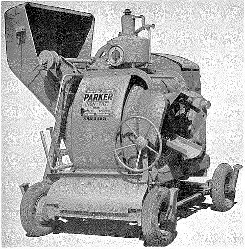
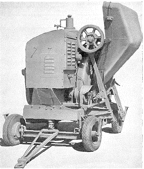
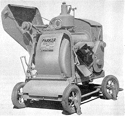
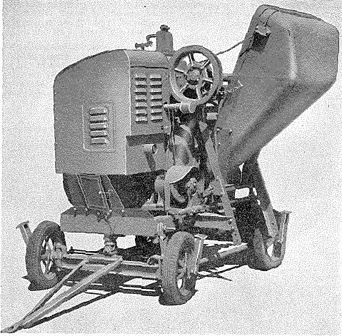
Parker concrete mixer,  Model 14/10

Parker concrete mixer,  Model 14/10 from rear rightParker concrete mixer,  Model 14/10 from front left
Description
  1. The Parker concrete mixer, Model 14/10, is a non-tilting type with a power operated side loading hopper, and a side discharge chute controlled by a hand lever.

  2. Power is supplied by a two-cylinder water-cooled diesel engine which drives the drum shaft through a clutch and roller chain; the drum is driven by a pinion on the drum shaft.

  3. An "Accurmeter" water tank measures the quantity of water for each batch. The tank operates on a syphon system and the height of the syphon can be adjusted to vary the amount of water delivered; a dial calibrated in pounds and gallons is fitted to the side of the tank to indicate the quantity.

  4. The machine is mounted on a four-wheeled, pneumatic tyred, trailer chassis. The front axle is pivoted at the centre to allow the axle to tilt on uneven ground; steering is effected through the tow-bar which is connected to the steering knuckles by track rods.

Stores Ref - 89D/15

MT required for transporting: -

  • SMT, 20 ton trailer (NOTE - This machine is not fitted with brakes so cannot be towed on public roads)

This item of equipment appears to have been added to the 2nd Edition by the issue of AL83.

Engine

Petter, Type AV2, 2-cylinder, water-cooled, Diesel engine:  BHP - 8 at 1,200 rpm /10 at 1,500 rpm

Operating Data

Batch capacity

  • Unmixed - 14 cu. ft.

  • Mixed - 10 cu. ft

Capacity of water tank -  13 gall

Dimensions

Charging opening - 1 ft. 11 in.

Diameter of drum - 4 ft. 3 in

Length of drum - 3 ft. 0 in

Technical Data

Dimensions (not shown above): -

  • Wheelbase (centres) - 6 ft 5 in

  • Track - 5 ft 0 in (front and rear wheels)

  • Minimum ground Clearance (under axle brackets) - 7½ in

  • Minimum turning circle (dia) - 34 ft 6 in.

Weights 

  • Total weight of machine empty - 2 tons 7 cwt

  • Front axle loading - 1 ton 9 cwt

  • Rear axle loading - 18 cwt


Parker concrete mixer Model 10/7

Description
  1. The Parker concrete mixer, Model 10/7, is a non-tilting type with a power operated side loading hopper, and a side discharge chute controlled by a hand lever.

  2. Power is supplied by a two-cylinder water-cooled diesel engine which drives the drum shaft through a clutch and roller chain; the drum is driven by a pinion on the drum shaft.

  3. An "Accurmeter" water tank measures the quantity of water for each batch. The tank operates on a syphon system and the height of the syphon can be adjusted to vary the amount of water delivered; a dial calibrated in pounds and gallons is fitted to the side of the tank to indicate the quantity.

  4. The machine is mounted on a four-wheeled, pneumatic tyred, trailer chassis. The front axle is pivoted at the centre to allow the axle to tilt on uneven ground; steering is effected through the tow-bar which is connected to the steering knuckles by track rods.

Stores Ref - 89D/23

MT required for transporting: -

  • SMT, 20 ton trailer (NOTE - This machine is not fitted with brakes so cannot be towed on public roads)

This item of equipment appears to have been added to the 2nd Edition by the issue of AL83.

Engine

Petter, Type AV2, 2-cylinder, water-cooled, Diesel engine:  BHP - 8 at 1,200 rpm /10 at 1,500 rpm

Operating Data

Batch capacity

  • Unmixed - 10 cu. ft.

  • Mixed - 7 cu. ft

Capacity of water tank -  9½ gall

Dimensions

Charging opening - 1 ft. 11 in.

Diameter of drum - 3 ft. 9¼ in

Length of drum - 2 ft. 9½ in

Technical Data

Dimensions (not shown above): -

  • Wheelbase (centres) - 5 ft 11 in

  • Track - 4 ft 8 in (front and rear wheels)

  • Minimum ground Clearance (under axle brackets) - 7½ in

  • Minimum turning circle (dia) - 30 ft 9 in.

Weights 

  • Total weight of machine empty - 2 tons 1 cwt

  • Front axle loading - 1 ton 5 cwt

  • Rear axle loading - 16 cwt


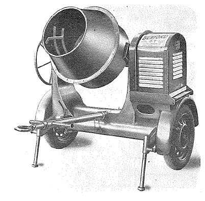
Benford, 3 cu ft Concrete Mixer, Model KR-12 (Trailer mounted)
Description
  1. This concrete mixer is a small mixer mounted on a pneumatic tyred, two-wheeled trailer chassis, fitted with internal expanding brakes which are operated on the over-ride principle.  The machine is designed for towing at speeds up to 30 mph.

  2. Two adjustable supporting legs with quick acting spring loaded stops are fitted to the front of the chassis for setting the machine level, and two safety legs are fitted at the rear of the chassis to steady it in the operating position.  The towbar, with the brake operating rod, is detached from the trailer when the machine is prepared for operation.

  3. The mixing drum is driven by a Villiers air-cooled gasoline engine which is mounted on the left-hand side of the chassis.  The power is transmitted through a chain and sprocket drive to an enclosed bevel shaft and bevel wheel which drives the mixing drum.  The tilting mechanism comprises a pinion and rack operated by a hand wheel

Stores Ref - 89D/25

MT required for transporting: -

  • Suitable for towing at road speeds up to 30 mph.

This item of equipment appears to have been added to the 2nd Edition by the issue of AL85.

Engine

Villiers, Model 12 RG, single-cylinder, side valve, air-cooled, petrol engine:  BHP - 1.2 at 2,000 rpm (governed)

Operating Data

Maximum capacity of drum - 5 cu. ft

Output of drum - 3 cu. ft. mixed per batch

Height of drum mouth in filling position - 3 ft. 5 in

Height of drum mouth in discharge position - 2 ft. 1 in.

Size of drum mouth - 1 ft. 7 in. (dia.)

Speed of mixing drum  - 20 rpm.

Clearance height for operating - 5 ft. 8 in

Dimensions - see below

Technical Data

Overall Dimensions

  • Length (with tow bar) - 5 ft 10 in.

  • Height (towing position) - 5 ft 0 in.

  • Width - 5 ft 5 in

  • Track - 4 ft 10 in

  • Height of towing eye - 23 to 32 in

  • Ground Clearance (under axle) - 11 in

Nett Weight - 952 lb


Koehring mixer and paver, 100 tph,

Koehring mixer and paver, 100 tph,

Description
  1. The paver consists of a power unit mounted on tracks, a standard charging skip, a delivery boom, a self -spreading bucket, a water measuring device and a batchmeter

  2. The batchmeter is a device which times and regulates the charging and mixing operations as well as the various pneumatic rams in the system.  Thus after the batchmeter is set and tripped, the cycle of mixing and discharge of the concrete is automatic.  Manual controls are fitted also so that the work may proceed without the use of the timing device if necessary.

  3. Power is supplied by a General Motors Diesel Engine Model 4-71 and a heavy-duty compressor provides the air for the pneumatic system.

MT required for transportation -

  • Hands or Templewood trailer (for transportation)

  • AEC, Matador, 4x4, Tractor (for Towing)

This item of equipment appears to have been added to the 2nd Edition by the issue of AL27.

Engine General Motors, Type 4-71, 4 cylinder, water cooled, Diesel engine:  Capacity - 283.7 cu in:  BHP - 103 at 1,800 rpm
Operation By the operation of the 2-speed lever, two forward speeds and one reverse are obtainable, and the speed over the ground in miles per hour are given in the following table:
Speed Position of 2-speed lever MPH
1 1 1
2 2
Reverse Reverse ¾

Mixing and discharge of the concrete is done automatically by the batchmeter, or operation of manual controls performs each phase of the cycle as necessary

Capacity of paver - 34 cu. ft.

Mixing time - Normally I mm.

Output - 50 batches per hour at 2 min mixing time, or a maximum output of 86.7 batches per hour at 1min. mixing time (56.5 cu. yd.)

Technical Data Running Gear (tracks)
  • Track centres - 10 ft 8½ in
  • Length (overall) - 15 ft 8¾ in
  • Width of one track - 9 ft 6 in
  • Shoe width - 1 ft 8 in

Working weight  - 48,580 lb

Overall dimensions: -

  • Length (skip and boom down) - 66 ft 1¼ in.

  • Length (skip and boom removed) - 19 ft 2¼ in.

  • Width (including platform)- 12 ft 1 in

  • Width (excluding platform)- 9 ft 11¼ in

  • Height (with skip lowered)- 11 ft 11 in

  • Height (with skip raised)- 25 ft 0 in


Foote mixer and paver, Multifoote Model 34E

Foote mixer and paver, Multifoote Model 34E

Description
  1. The Foote mixer and paver, Multifoote Model 34E, is designed to mix concrete and distribute it to pave roads, airfield runways, floors, etc.  The machine moves on tracks under its own power, and is thus enabled to keep up with work as it progresses.

  2. Power to operate the mixer and paver is provided by a Hercules gasoline engine, Model RXLD.

  3. The main components of the mixer and paver are: -

    1. Loading skip

    2. Mixing drum

    3. Discharge chute

    4. Boom and bucket

    5. Water system

    6. Running gear

    7. Batchmeter

  4. The loading skip receives the batch, i.e. the sand, gravel and cement, from the trucks.  The skip pivots on a hinged mechanism and is capable of being raised, so that its throat projects into the rear opening of the drum into which the batch is poured.  The concrete is mixed in the drum from where the concrete passes to the bucket, by way of the discharge chute.

  5. The water system consists of tanks and mechanism for feeding water into the drum.  The quantity of water is gauged by a measuring tank.

  6. The controls are all arranged on the operator's platform.

MT required for transportation -

  • Rogers, 40 ton, trailer (for transportation)

This item of equipment appears to have been added to the 2nd Edition by the issue of AL39.

Engine Hercules, Type RXLD, 6 cylinder, water cooled, Diesel engine:  Capacity - not stated:  BHP - 1not stated
Machine Specification Running gear - Two tracks

Main engine clutch - Twin disc type

Steering system - Steering brakes located under the skip end of the machine

Loading skip - Located and hinged at rear of machine

Mixing drum - Double-cone type

Discharge chute - Discharges concrete into the bucket

Boom and bucket - Bucket is suspended from the boom and has a 6-in. spreading radius.  The boom can swing left or right in a 160 degree arc and can also be raised and lowered.  The bucket discharge doors are operated by cable control

Water system - Consists of tanks and mechanism for storing and feeding a predetermined amount of water at the right time for each batch.

Batchmeter - Times the mix, locks the discharge chute in the closed position until the mixing time is completed, and then unlocks it, rings a gong to signal to the operator when the mix is completed, and records on a counter the total number of batches mixed.

Controls:

Drive and adjustment - Drum drive sliding gear lever; power take-off lever; water measurement clutch control lever; and the water measurement control lever

Charge, mix and discharge - Boom swing and lift shifter clutch lever; boom swing or lift lever; skip hoist lever; skip hoist ratchet lever; skip hoist auxiliary lever; boom bucket lever; power discharge lever; water control lock lever; and water control lever

Traction - High and low speed pedal; forward and reverse lever; traction friction clutch lever; steering clutch lever; left steering brake pedal; left steering brake control lock ratchet; right steering brake pedal; and right steering brake control lock ratchet

Methods of operating - Automatic or manual

Technical Data

Weight-

  • Base machine (water tank built in) - 18 tons 17 cwt

  • Boom - 18¼ cwt

  • Bucket - 1 ton 2¼ cwt

  • Skip - 1 ton 7 cwt

Dimensions: -

  • Base machine (water tank built in)

    • Length - 26 ft 9 in.

    • Width - 11 ft 4 in

    • Height - 12 ft 7 in

  • Boom

    • Length - 36 ft 0 in.

    • Width - 2 ft 6 in

    • Height - 1 ft 3 in

  • Bucket

    • Length - 4 ft 8 in.

    • Width - 5 ft 6 in

    • Height - 6 ft 0 in

  • Skip

    • Length - 17 ft 8 in.

    • Width - 10 ft 1 in

    • Height - 4 ft 0 in


Blaw-Knox concrete spreader, Model SA

Blaw-Knox concrete spreader, Model SA

Description
  1. The Blaw-Knox concrete spreader is designed to operate directly behind a paving mixer, and in advance of a finisher.  The machine moves along rails or forms, and spreads the intermittent batch output of the paver in a continuous uniform slab of concrete.

  2. The spreader has two main working units, the remaining parts of the machine exist for the sole purpose of effecting the efficient operation of the two main units.  The two main working parts are:

    1. The blade which spreads the paver batches across the road as the machine advances along the forms.

    2. The strike-off plate, with its integral end wings, which is arranged so that it leaves a surface of approximately the final contour.

  3. The transmission is of the selective sliding spur gear automotive type, which provides four traction speeds forward and a reverse, as well as one speed for the trolley drive.  Roller chain drives are used throughout.

  4. The wheel hubs are equipped with double-flange split type wheels for use on forms.  The hubs can be quickly, removed and replaced by flat tread wheels and rims, for placing concrete between two existing concrete slabs.

  5. The trolley is mounted on the cross-members, and as it approaches the end of its travel across the roadway, the direction of travel and position of the spreading blade is automatically reversed.  A crown and jump track serves to lift the blade when it is necessary to clear any steel longitudinal centre joints.

  6. The strike-off plate is mounted in the back of the trolley. It is provided with hydraulic control for elevation setting and other adjustments required to give the various road contours, and also to leave the concrete for minimum finisher operation.

  7. The machine is powered by a Continental 6-cylinder gasoline engine, Type PF.226

  8. All the controls are centralised about the operator's platform.

MT required for transportation -

  • SMT, 20 ton, trailer (for transportation)

This item of equipment appears to have been added to the 2nd Edition by the issue of AL39.

Engine Continental, Type PF226, 6 cylinder, water cooled, petrolengine:  Capacity - 226 cu in:  BHP - not stated
Machine Specification Power take-off - Straight through drive to main transmission.

Clutch - 10 in Single plate (twin disc), toggle operated type with ball bearing thrust collars

Transmission (four speed)

  • Low - 7.75 ft/min
  • 2nd - 11.8 ft/min
  • 3rd - 14.1 ft/min
  • 4th - 86.8 ft/min
  • Trolley speed - 187 ft/min

Wheels - 4 x Double-flanged split type, flat split type or Closure split type.

Controls

Mechanical  - Ignition switch, choke rod, governor control lever, main clutch and brake control lever, forward and reverse lever, first and third speed lever, first or third and second speed lever, fourth speed lever, trolley lever, steering clutch and brake levers, trolley handwheel and power unit oil pressure indicator

Hydraulic - Strike-off lift valve, regulating valve and hydraulic pressure gauge

Technical Data

Weight-

  • Base machine (water tank built in) - 18 tons 17 cwt

  • Boom - 18¼ cwt

  • Bucket - 1 ton 2¼ cwt

  • Skip - 1 ton 7 cwt

Dimensions: -

  • Length - 24 ft 0 in.

  • Width - 10 ft 6 in

  • Height - 6 ft 9 in

  • Volume - 1,501 cu ft


Blaw-Knox concrete finisher, Model XC

Blaw-Knox concrete finisher, Model XC

Description
  1. The Blaw-Knox concrete finisher is designed to work in conjunction with a concrete paver and a spreader.  It moves along the forms behind the spreader, and gives the final finish to the surface of the slab which was laid and spread by the paver and spreader, respectively.

  2. The transmission is of the selective sliding spur gear automotive type and provides six traction speeds forward and a reverse.  To ensure maximum flexibility four screed speeds are also provided.  The drives are of the roller chain type throughout.

  3. The front screed is 9 in, wide and the rear is 12 in. wide.  Both screeds have large end wings to minimise spillage of concrete over the road forms. Coil springs are incorporated in the screed drive rods, to absorb the shock of the screed reversal at the ends of the stroke.

  4. The machine is equipped with a surface vibrator, having two cellular type vibratory members each actuated by two adjustable vibratory units.  The vibrator drive is by means of multiple V-belts, and all vibrator shafts are mounted on ball bearings.

  5. The wheels are equipped with detachable rims, with single outside flanges.  The rims cant be quickly removed and replaced by rims with double flanges, rims  without flanges, or by special types of rims for specific purposes.

  6. A power hydraulic system is incorporated in the machine for the purpose of lifting the screeds and vibrator.

  7. All instruments and controls are grouped around the operator's seat.

MT required for transportation -

  • SMT, 20 ton, trailer (for transportation)

This item of equipment appears to have been added to the 2nd Edition by the issue of AL42.

Engine Hercules, Type IXB-5, 4 cylinder, water cooled, petrol engine:  Capacity -133 cu in:  Compression ratio - 5.92 to 1: BHP - not stated
Machine Specification Clutch - Single plate, roller operated type

Transmission - Six traction speeds and four screed speeds

Traction Speeds

  • 1st - 7.4 ft/min
  • 2nd - 9.9 ft/min
  • 3rd - 12.5 ft/min
  • 4th - 16.5 ft/min
  • 5th - 76.7 ft/min
  • 6th - 101.1 ft/min

Screed Speeds (strokes per min)

  • 1st - 48
  • 2nd - 60
  • 3rd - 64
  • 4th - 79

Speed of rotation of vibrator units (frequency) - 4,100 rpm

Technical Data

Weight-

  • Finisher in working order - 12,000 lb

  • Moving truck - 1,700 lb

  • Deadweight - 13,000 lb

Dimensions: -

  • Tread (inside of forms, adjustable +/- 1 in) - 20 ft 0 in

  • Length (with front screed in place) - 11 ft 1 in.

  • Length (with front screed removed) - 9 ft 6 in.

  • Width - 22 ft 7 in

  • Height - 6 ft 2 in

  • Volume - 1,394 cu ft


Foote mixer and paver, Multifoote Model 27E

Foote mixer and paver, Multifoote Model 27E

Description
  1. The Foote mixer and paver, Multifoote Model 27E, is a smaller model, of the Multifoote Model 34E described above and is fitted with similar components which generally are of lower capacity.  Power for this model is provided by a Hercules gasoline engine, Model RXC.

This item of equipment appears to have been added to the 2nd Edition by the issue of AL52.

Engine Hercules, Type RXC, 6 cylinder, water cooled, petrol engine:  Capacity -529 cu in:  BHP - 131.5 at 2,300 rpm
Machine Specification

Running gear - Two tracks

Main engine clutch - Twin disc type

Steering system - Steering brakes located under the skip end of the machine

Loading skip - Located and hinged at rear of the machine

Mixing drum - Double cone type

Discharge chute - Discharges concrete into the bucket

Boom and bucket - The boom can be swung right or left in a 160 deg. arc, and can also be raised and lowered.  The bucket has a 6 in. spreading radius; the bucket discharge doors are operated by cable

Water system - Consists of tanks and mechanism for storing and feeding a predetermined amount of water at the right time for each batch

Batchmeter - Times the mix, locks the discharge chute in the closed position until the mixing time is completed, and then unlocks it, rings a gong to signal to the operator that the mix is completed and records on a counter the total number of batches mixed

Controls

  • Drive and adjustment - Drum drive sliding gear lever; power take-off lever; water measurement clutch control lever; water measurement control lever

  • Charge, mix, and discharge - Boom swing and lift shifter clutch lever; boom swing or lift lever; skip hoist lever; skip hoist ratchet lever; skip hoist auxiliary lever; boom bucket lever; power discharge lever; water control lock lever; water control lever

  • Traction - High and low speed pedal; forward and reverse lever; traction friction clutch lever; steering clutch lever; left steering brake pedal; left steering brake control lock ratchet; right steering brake pedal; right steering brake control lock ratchet

Technical Data

Weight- not stated

Dimensions: - not stated


Johnson tamping and screed board vibrator, Model 3

Johnson tamping and screed board vibrator, Model 3 - working order

Description
  1. The vibrator is designed for fitting to a screed board for use in compacting concrete by a tamping action and by vibration.  The vibration assists the board to travel and the speed of travel will vary according to the grading and moisture content of the mix, and the gradient on which work is being done.

  2. The machine consists of a vibrator unit complete with an air cooled gasoline engine, two screed board handles, an engine remote control, two return rollers, brackets, bolts and fittings for attaching the parts to a screed board. Screed boards are not supplied with the machines and must be obtained from local resources.

  3. The engine is secured to the vibrator unit by four anti-vibration springs, and drives the vibrator rotor by a single v-belt. The screed board handles incorporate springs and rubber handgrips to prevent vibration from being transmitted to the operators; the engine remote control is attached to one of the handles.

MT required for transportation

  • Light truck or as part load on a 5 ton tipper

This item of equipment appears to have been added to the 2nd Edition by the issue of AL79.

Engine Villiers, Mark 10, single-cylinder, side valve, air-cooled, petrol engine:  BHP - 1.3 at 3,000 rpm (governed)
Operating Data

Operative width for a screed with one vibrator unit - 16 ft. Max. (between road forms)

Operative width for a screed with  two vibrator units - 21 ft. Max. (between road forms)

Vibrating frequency - 4,000 vibrations per min.

Vibrating amplitude - 0.13 inches

Vibrating acceleration 5.9G

Self travelling speed   20/30 ft. per min.

Dimensions

  • Overall height (machine and board) - 2 ft. 4 in

  • Overall width (width of handles) - 2 ft. 0 in.

  • Depth of board - 9 in.

  • Width of board - 3 in.

Johnson tamping and screed board vibrator, Model 3 - engine

Technical Data

Engine and vibrator unit (uncrated)

  • Overall height - 1 ft. 9 in.

  • Overall width - 1 ft. 4 in

  • Overall length - 2 ft. 4 in.

Handles, rollers and fittings (crated)

  • Overall height - 2 ft. 6 in

  • Overall width - 2 ft. 3 in

  • Overall length - 1 ft. 4 in

Weights

  • Engine and vibrator unit - 96 lb.

  • Handles (each) - 28 lb

  • Rollers (each) - 4 lb.

  • Total weight of machine (uncrated) - 175 lb


Holman Concrete Compactor Model CC2/Holman Screed Board Vibrators, Models CC2 & CC3

Holman Concrete Compactor Model CC2

Description
  1. The Holman screed board vibrators, Models CC.2 and CC.3, are air-operated plate-type vibrators for the compaction of flat, horizontal or near-horizontal concrete surfaces such as occur on roads, runways or floors etc.

  2. Each machine consists basically of a long U-shaped steel channel, forming a screed board, attached to a steel batten by spring-loaded retaining pins.

  3. On Model CC.2, two piston and anvil bar assemblies, on Model CC.3, three piston and anvil bar assemblies, each consisting of a vertical cylinder in which an air-operated piston is allowed to reciprocate, are bolted to the top face of the batten so that each piston at the end of its down stroke strikes the head of an anvil bar mounted in a guide in the batten and resting on an anvil plate welded to the channel.  The impact of the piston on the anvil bar is transmitted through the anvil plate to the channel and provides a tamping effect on any material on which the channel is resting.

  4. The pistons reciprocate continuously all the time that the control valve of the tool is open, provided that the weight of the vibrator is taken by its working face.  If the channel is allowed to hang from the batten, as when the vibrator is lifted from the job, the air supply to the piston and anvil bar assemblies is cut off by the action of a contact valve mounted in the batten.  A screw-type control valve is provided for normal on/off control.  Air is supplied to the vibrator through an air adapter at the end of one of the handles.

  5. Two operators are required for the vibrator; the operators hold the handles at each end of the tool and guide and steady it over the surface of the wet concrete.  Under favourable conditions, with a low water-cement ratio, the compacting effect will extend to a depth of 8 or 9 in. below the surface of the concrete and the compacted concrete can be stood on immediately without making any indentation.

  6. These vibrators leave a ribbed surface which assists in the prevention of skidding or for the "keying" of a subsequent coat of asphalt or tarmacadam. No attempt should be made to obtain a smooth surface with these particular vibrators; if a smooth surface finish is desired, a finishing screed must be used after compaction has been effected.

The CC2 appears to have been added to the 2nd Edition by the issue of AL88 but this was joined by the CC3 in AL94, to which this entry has been amended.

Technical Data

Maker's designation  - Concrete compactors, Symbol CC.2 and CC.3

Air adapter - ¾ in. BSP male

Channel length           

  • Model CC.2 - 12 ft. 0 in.

  • Model CC.3 - 15 ft.   6 in.

Channel width - 4 in.

Overall length

  • Model CC.2 - 16 ft. 4 in.

  • Model CC.3 - 19 ft. 10 in

Overall width - 1 ft. 8 in.

Weight

  • Model CC.2 - 290 lb.

  • Model CC.3 - 380 lb.

Free air consumption at 80 lb. per sq. in.        

  • Model CC.2 - 40 cu, ft. per mm.

  • Model CC.3 - 60 Cu. ft. per ruin.

Maximum bay, width for effective compaction        

  • Model CC.2 - 11 ft. 6 in.

  • Model CC3 - 15 ft. 0 in.


Climax poker vibrator, Model A70

Climax poker vibrator, Model A70

Description
  1. The Climax poker vibrator, Model A.70, consists of an air-operated vibrating mechanism enclosed in an air and water-tight vibrator head that can be completely immersed in wet concrete so that compaction of the concrete is effected.

  2. The tool is particularly suitable for the compaction of concrete that has been poured into moulds or shuttering for the production of pillars, walls, etc., and its use enables an extremely low water-cement ratio concrete to be compacted successfully.

  3. The presence of reinforcing steelwork has no effect on the action of the vibrator; the vibratory effect being transmitted through the steel to the concrete beyond.

  4. Air is supplied to the tool through a combined throttle valve and lubricator assembly connected to the vibrator head by two 10 ft. lengths of rubber hose, one inside the other, carrying pressure and exhaust air respectively.

Stores Ref - 89D/53

This item of equipment appears to have been added to the 2nd Edition by the issue of AL94.

Technical Data

Maker's designation - Pneumatic vibrator, Type A.70

Air adapter - ½ in. BSP male

Control - Push-button-type throttle valve

Recommended air pressure - 75 to 100 lb. per sq. in.

Air consumption - 35 cu. ft. of free air per mm. at 90 lb. per sq. in. pressure

Lubrication - One oz. capacity lubricator mounted as a unit with the throttle handle

Frequency - 11,500 rpm approx

Capacity - Up to 16 cu. yd. of Concrete per hour

Dimensions

  • Vibrator head - 15 in. by 2¾ in.

  • Hose - 10 ft. length, concentric

Weight

Complete with hose, throttle handle, and lubricator - 34 lb.


Holman Core cutter, Model BB

Holman Core cutter, Model BB

Description
  1. The core cutter is designed to cut sample cores from hardened concrete to enable laboratory tests to be carried out and to provide a method of inspecting the quality and depth of the concrete. The concrete is cut wet and a water supply is required for supplying a pump on the cutter; shot drilling technique is employed using No 8 chilled steel shot with a shot bit.

  2. The cutter unit is carried on a frame comprising two heavy longitudinal channels which pass under the axles and are bolted to the tractor implement pads. Two cross members support the cutting unit, and a third cross member provides a towing attachment.  A chain drive from the tractor rear Power Take-off drives the cutting head.

  3. Although normally fitted to a Fordson Major Tractor, the cutter can be fitted to other vehicles with a suitable power take-off.  Four jacks are provided to steady and set the cutter level; the jacks can be retracted for travelling.

Stores Ref - 89D/64

This item of equipment appears to have been added to the 2nd Edition by the issue of AL99.

Machine Specification

Make and Model - Holman Model BB

Type  - Shot drilling, core cutter

Operating Data

Holman Core cutter, Model BB - dimensions

Diameter of shot bit - 6 in.

Max. depth of core - 13 in.

Shot size - No 8 chilled shot

Operating speed

  • Commencing cut - 60/70 rpm.

  • Maximum speed - 120/150 rpm.

  • Water supply - A supply of 250 gal. is required for cutting a core from 12 in. concrete

Dimensions (Working condition) Fordson tractor fitted with cutter

  • Overall length - 11 ft. 4 in

  • Overall width - 5 ft. 8 in

  • Overall height (top of feed screw) - 7 ft.

Technical Data

Dimensions (crated for shipment)      

Core cutter - 84 in. x 20 in. x 24 in.

Jacks and frame members - 80 in. x 18 in. x 14 in.

Weight (total crated) - 1,130 lb.

The dates of the various Amendment Lists are shown below: -

Amendment List

Date of issue

Amendment List

Date of issue

Amendment List

Date of issue

Amendment List

Date of issue

1

 Mar 1951

26

Nov 1951

51

Aug 1952

76

 Mar 1956

2

May 1951

27

Nov 1951

52

Nov 1952

77

May 1956

3

Jul 1951

28

Nov 1951

53

Mar 1953

78

May 1956

4

Jul 1951

29

Nov 1951

54

Mar 1953

79

Jun 1956

5

Aug 1951

30

Nov 1951

55

Mar 1953

80

 Jul 1956

6

Sep 1951

31

Dec 1951

56

Apr 1953

81

Aug 1956

7

Sep 1951

32

Dec 1951

57

Apr 1953

82

Aug 1956

8

Sep 1951

33

Dec 1951

58

Jun 1953

83

Sep 1956

9

Sep 1951

34

Dec 1951

59

Jun 1953

84

Dec 1956

10

Sep 1951

35

Dec 1951

60

Jul 1953

85

Apr 1957

11

Sep 1951

36

Dec 1951

61

Sep 1953

86

Jul 1957

12

Sep 1951

37

Dec 1951

62

Sep 1953

87

Jul 1957

13

Sep 1951

38

Dec 1951

63

Feb 1954

88

Oct 1957

14

Sep 1951

39

Dec 1951

64

Mar 1954

89

May 1958

15

Sep 1951

40

Dec 1951

65

Aug 1954

90

May 1958

16

 Sep 1951

41

Dec 1951

66

Sep 1954

91

Aug 1958

17

 Sep 1951

42

Jan 1952

67

Oct 1954

92

Sep 1958

18

Oct 1951

43

Jan 1952

68

Oct 1954

93

Dec 1958

19

Oct 1951

44

Feb 1952

69

Dec 1954

94

Feb 1959

20

Oct 1951

45

Mar 1952

70

?

95

Mar 1959

21

Nov 1951

46

Apr 1952

71

?

96

Feb 1959

22

Nov 1951

47

May 1952

72

Sep 1955

97

Apr 1959

23

Nov 1951

48

Jun 1952

73

Nov 1955

98

Jul 1959

24

Nov 1951

49

Jun 1952

74

Nov 1955

99

Nov 1960

25

 Nov 1951

50

Jul 1952

75

Feb 1956


This page was last updated on 08/07/19

[Top of Page]